Wednesday, August 10, 2022

Fet Turbo Timer Wiring Diagram

The solenoid has and in and out, and then the wire running back to the control module. Hook up the harness to your turbo timer (it should be the only connector with same male/female ends).


Blitz Fatt Turbo Timer Wiring Diagram Wiring Diagram

There should be a black ground wire somewhere coming off the tt.

Fet turbo timer wiring diagram. Below is the turbo timer wiring diagram, refer to your specific turbo timer instructions for installation. Simple electronic keyer wiring diagram schematic; Wiring diagram,installation for comtec 125 by nizam tuesday, august 25 2009 6:31 am.

Turbo timer ( µtear off paper on backside of adhesive äinstall turbo timer near to control panel confirm wiring method first, then installation place. Put black/ground wire onto a metal surface w/out paint. Install car stereo satellite radio;

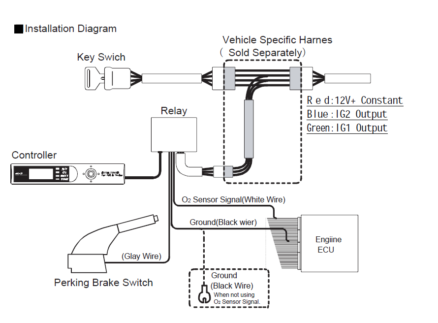
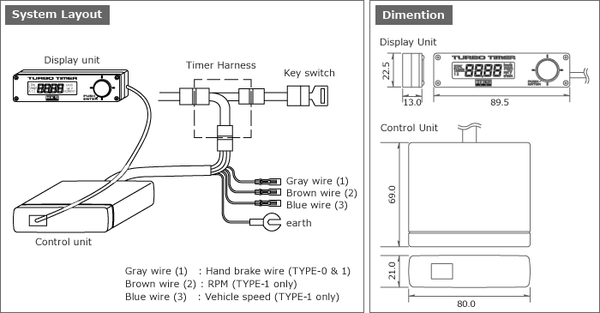
( please refer to the vehicle specific wiring diagram. Whether you have a turbocharged sports car, a turbo diesel truck or even a turbo wagon, the hks turbo timer iv is a must. To ensure capability of components inside, please don't.

Wiring diagram or fitting instructions by kanishka weerathunge thursday, november 25 2010 3:06 am. 9) many turbo timers only operate if the parking brake is set. Vy stereo wiring diagram / holden commodore vy 2003 fuse box block circuit breaker diagram carfusebox / 1 way light switch wiring diagram;

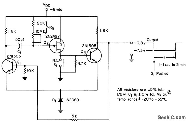
Stereo to mono converter based on fet ?it only has one start/select button on it and a handbrake switch to start it automatically when you pull up and park.you can. Q1 acts like a constant current source, and begins slowly charging c1 at a steady constant current rate.

Introduction to the turbo timer: Find resources for government, residents, business and visitors on hawaii.gov. Need a diagram for a turbo timer bypass.problem i have a evo 8 with a viper hf350 alarm apexi turbo timer, i want to arm my system while turbo timer is still running.this car is a jdm model right hand drive.

It will not work on other car years or model that is not listed. Extend it with more wire if necessary, but be sure to find a good ground for your tt on any bolt on the frame of the car, or in the ecu ground wires. Saas make a large range of

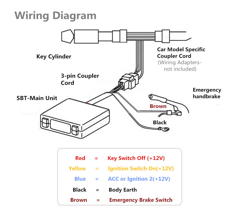
Gas fireplace wiring diagram : (1) connect the brown wire from the turbo timer to the supplied brown rpm signal lead wire. (2) refer to the corresponding vehicle list to find the correct ecu diagram.

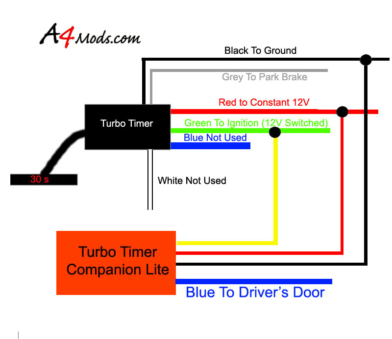
Simple 555 timer circuit key cod; Simple sound scanner wiring diagram schematic; For tt's with 3 connections black yellow and red.

The rate of charging of c1 is determined by the resistance of the pot p1. Next, take off your kick panel and take apart ignition connectors, plug the harness into that. Parking brake just splice into the wire coming directly off of the sensor.

To connect the turbo timer you must ground your tt to the chasis the tt red goes to either the iginitons black red or beefy brown the tt yellow goes with the iginitons black with yellow stripe aka ig2 the tt blue (or accesory) goes to the ignitons brown with white stripe. 8) you must also ground your turbo timer. Fet turbo timer wiring diagram :

The diagram above shows basic mosfet timer circuit. Hks turbo timer wire are design for hks turbo timer, apexi turbo timer or some models of greddy turbo timer and it is plug and play connect turbo timer to your car. Be time 125 diagram by chalermpon saturday, april 12.

Connect the 3 prong timer harness to the relay. Digital turbo timer page 1/3 wiring guide: Mini fm transmitter wiring diagram schematic;

(except the universal model wire) also the turbo timer wire only work for the model we list below. How it works when power is switched on c1 grounds the fet gate, keeping it switched off. Solve buzzing and noise on the amplifier circuit;

Diagram of comtec betime 125 turbo timer by adrian carl nitron wednesday, january 13 2010 4:49 pm.


Hks Turbo Timer Type 0 Wiring Diagram


Turbo Timer Wiring Diagram


ขาย TURBO TIMER FET TB208 AUTO TIMER


Turbo Timer Wiring Diagram Complete Wiring Schemas


Turbo timer question HondaTech Honda Forum Discussion


Turbo Timer Schematic Diagram Wiring View and Schematics Diagram


FET_TIMER Electrical_Equipment_Circuit Circuit Diagram


على حد سواء رطل شريط greddy turbo timer wiring diagram


Turbo Timer Wiring Diagram Complete Wiring Schemas


Turbo Timer Wiring Diagram Complete Wiring Schemas


ขาย TURBO TIMER FET TB208 AUTO TIMER


How To Making the Greddy Turbo Timer coexist with your alarm Page 2… Turbo timer, Greddy


Turbo Timer Install/wiring The Ranger Station Forums


Turbo Timer Wiring Diagram


Hks Turbo Timer Type 0 Wiring Diagram


Mosfet Timer Circuit Simple and Easy to Make Electronic Circuit


Blitz Fatt Dc Turbo Timer Wiring Diagram Style Guru Fashion, Glitz, Glamour, Style unplugged


Blitz Fatt Dc Turbo Timer Wiring Diagram Wiring Diagram and Schematic


Wiring my Turbo Timer Maxima Forums

Hid Edge Evo Eh400 K Wiring Diagram

D.3 edge evo is the next evolution in access control hardware solutions. Edge evo is the next evolution in access control hardware solutions.


How to default an HID EH400K unit YouTube

Edge evo is the next evolution in access control hardware solutions.

Hid edge evo eh400 k wiring diagram. Edge evo is the next evolution in access control hardware solutions. A true ip solution that meets the demands of. Hid eh400k dual reader wiring diagram.

Hid edge evo ehk standard controller installation guide manuals and user guides for free. About press copyright contact us creators advertise developers terms privacy policy & safety how youtube works test new features press copyright contact us creators. Hid v wiring diagram 24 wiring diagram from hid card reader wiring hid card reader wiring diagram beautiful hid edge evo wiring.1.

I didn't see any videos to allow myself to research my first installation with multiple setups, so i made my own and i hope it helps someone else. The v physical rs port 1 and 2 reside on logical bus 1 (p3), while port 3. This vertx installation wiring diagram is intended as an example only, and should not be interpreted as an hid corporation recommendation.

The hid edgeplus ip access solution puts control and host interface right at the door. The panel is roughly the size of an r40 hid iclass reader and is mountable. To the door, leveraging the it infrastructure to the maximum extent possible.

The edgeplus e400 is a true ip access solution that manages up to 44,000 cardholders or credentials in. 83.8 x 121.9 x 36.3. Page 1 of 1 start over.

10 x smartcafe expert k dual cards, 1 x sdi usb reader, 1 x g&d usb reader, installation instructions & wiring diagrams. Hid, the hid logo, iclass. Read online or download in pdf without registration.


1 internal tamper disable jumpers, 2 relay jumpers, 3 tamper (reader interface board) HID EDGE


Regulatory, Access experience, Hid global HID EDGE EVO Solo ESH400K Networked Controller


1 power analysis, Step 1 identify system components, Step 2 create system layout HID


4 door module groups 1 & 2, 5 door interface board groups 1 & 2, Standard networked controller


2 mounting, 3 wiring, Mounting HID EDGE EVO EHR40EHRP40 ReaderController Installation


Hid Eh400k Wiring Diagram


HID EDGE EVO EH400K Standard Controller Installation Guide User Manual 12 pages


6 configure, 7 power & testing, Hio interface modules HID EDGE EVO Solo ESH400K


Regulatory, Access experience, Hid global HID EDGE EVO EH400K Standard Controller


HID Edge EVO Eh400k Standard Networked Controller 82000cke1a for sale online eBay


EDGE EVO YouTube


1 power analysis, Step 1 identify system components, Step 2 create system layout HID


Panasonic HIDEDGEEVOEH400 EH400K Networked Controller Interface to Standard Door REX, DPS


1 internal tamper disable jumpers, 2 relay jumpers, 3 tamper (reader interface board) HID EDGE


1 power analysis, Step 1 identify system components, Step 2 create system layout HID


2 mounting, 3 wiring, Mounting HID EDGE EVO Solo ESH400K Networked Controller


Step 4 select power scheme, Hio networked controller & reader, Installation guide 4 HID


Hio interface modules, Glossary, Standard networked controller HID EDGE EVO EH400K Standard


HID® EDGE EVO® Solo ESH400K Networked Controller HID Global

Tuesday, August 9, 2022

Vmax Wiring Diagram

Click on thumbnails below to see larger image, pages will open in a new window. If there are any additional pages you need just let me know and i will post them on this site.


Yamaha Vmax Wiring Diagram Wiring Diagram Schemas

You'll need a wiring diagram to do it correctly.

Vmax wiring diagram. Vmax 1200 tach wiring diagram. Yamaha vmax wiring diagram wiring schematic diagram wwww laiser how to fix snowmobile problems won t start stalls etc polaris clymer repair manual for yamaha vmax v max 1985 2003 yamaha wiring diagram yzf1000r 1997 ebay yamaha t max wiring diagram auto electrical wiring diagram yamaha 125 atv wiring diagram wiring diagram echo. Yamaha vmx1200 vmax online service manual.

Wired it into the stock tach wiring. Nov 2, i am running a 3 3/8 autometer procycle tach on toxic. Vmax odyssey gatherings south africa.

I have seen a fuel pump feed back through the tach and blow main fuses, again on the yamaha fj. Apr 23, 2011 #1 would any one. This is on an 89 fj and i don't know if a vmax uses the same setup.

Velvac mirrors wiring wiringall.com · click image for larger version name: 1994 yamaha vmax motorcycle wiring diagram. Click on document yamaha vmx12 v.

Vmax pix gallery 1st generation. Transmission, middle gear and internal shift mechanism this chapter covers the disassembly and inspection of the transmission shaft assemblies, middle drive gear assembly, middle driven gear assembly and. Large a3 (12 x 16) laminated colour wiring diagrams for yamaha vmax 12e 12ec general.

It is electrically the same, but much easier to follow as the wires can be laid out better. Illustrated symbols to in the exploded diagrams indicate the where to apply locking agent fuel sender unit tachometer fuse (fan) thermo switch fan motor fuse (head) control. This is the highly detailed factory service repair manual for the1994 1995 1996 yamaha vmax 500/600, this service manual has detailed illustrations as well as step by step instructions,it is 100 percents complete and intact.

Vmax 1200 tach wiring diagram. When you make use of your finger or perhaps the actual circuit with your eyes, it is easy to mistrace the circuit. Yamaha vmax full colour laminated wiring diagram pictures displayed are taken from various diagrams and are not indicative of any particular models.

Joined aug 25, 2008 messages 57 reaction score 0 location montreal. Start date apr 23, 2011; Print the wiring diagram off plus use highlighters to trace the signal.

I could only load a screen capture of these. Magneto rectifier/regulator main switch load relay fuse (main) fuse (fuel injection system) starter relay starter motor battery diode engine stop switch throttle switch grip warmer thumb warmer oil presser switch fuse (electronic control suspension) electronic control suspension solenoid e.c.u. (1) black/white (b/w) (with colored tags) wiring diagram for those of you that hate those hard to read, color yamaha wiring diagrams and for the color blind.

Hate those hard to read, color yamaha wiring diagrams and for the color blind. Yamaha vmax 12e 12ec general spec colour wiring diagram product no.: Mobile device ready manual* (works with most devices, click here and see question #5 for details) only $8.50:

Ignition coil #1 ignition coil #2 Vmax colour motorcycle wiring loom diagrams regarding fj1200 wiring diagram by admin from the thousands of images online in relation to fj1200 wiring diagram, we all selects the best series using ideal quality simply for you, and now this pictures is usually among graphics choices in your greatest pictures gallery regarding fj1200 wiring diagram. Ducati diavel carbon, abs '11 service manual.


Yamaha Vmax Wiring Diagram Wiring Diagram Schemas


Instrument panel connectors bypass? Yamaha Star VMax VMAX Motorcycle Discussion Forum


Fixing Headlight Wiring Yamaha Star VMax VMAX Motorcycle Discussion Forum


Vmax wiring diagram Snowmobile Forum Your 1 Snowmobile Forum


Yamaha Vmax Wiring Diagram Wiring Diagram Schemas


Yamaha Vmax Wiring Diagram Wiring Diagram Schemas


Vmax 1200 Tach Wiring Diagram


Yamaha Vmax 12N 12NC Colour Motorcycle Wiring Diagram


96 Yamaha Vmax 600 Wiring Diagram Wiring Diagram


12+ 1994 Yamaha Vmax Motorcycle Wiring Diagram Motorcycle Diagram in 2020


Pin on Motorcycle wiring


1994 Yamaha Vmax Motorcycle Wiring Diagram Database Wiring Diagram Sample


Yamaha Vmax Wiring Diagram Wiring Diagram Schemas


Yamaha Vmax Wiring Diagram Wiring Diagram Schemas


Yamaha Vmax Wiring Diagram Wiring Diagram Schemas


Yamaha Vmax Wiring Diagram Yamaha Vmax Wiring Diagram Wiring Diagram Schemas / 1992 fzr 600


Yamaha Vmax Wiring Diagram Wiring Diagram Schemas


Vmax 1200 Tach Wiring Diagram


[MZ_6123] Vmax Wiring Diagram Schematic Wiring

11 Pin Timing Relay Wiring Diagram

Rj11 Socket Wiring Diagram Australia, How to punch down an RJ11 Telephone Jack, 6.36 MB, 04:38, 387,634, CableSupply.com, 2009-08-05T00:16:...