Use the and arrows to change user. The wiring diagram is vague and seems amiss with regards to the initiate switch wiring shown between the r wiring and g wiring.
Any HVAC gurus on here? Looking for help with wiring a thermostat The Hull Truth Boating and
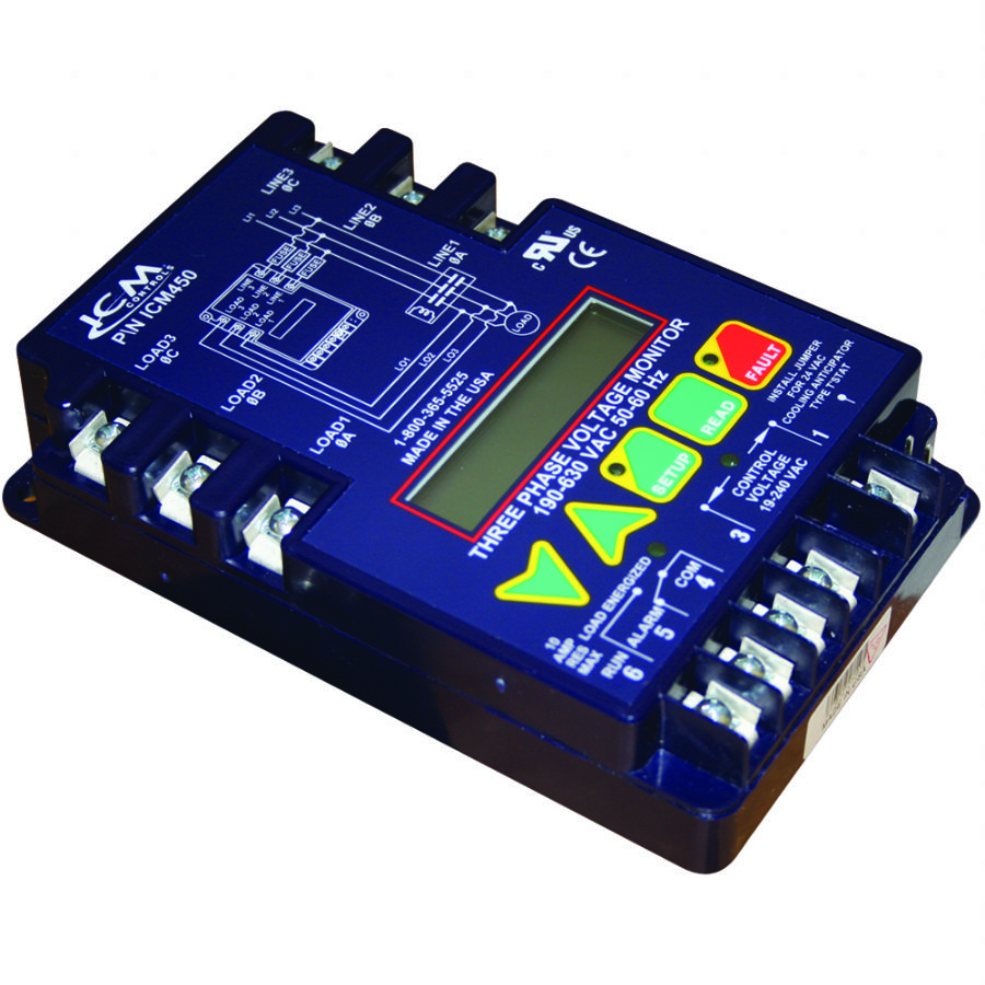
Icm401 typical wiring diagram typical part winding start wiring diagram with an icm450 and icm401 note:

Icm450 wiring diagram. Rebuild them & put them in an 88 4 cyl mustang. Lennox air handler wiring diagram; * use icm401 for 24 vac control voltage only icm401* icm450 6 4 3 line 1 0a line 0b line 0c load 0c load 0b load 0a 24 vac com l1 l3 l2 cc1 cc2 aux.
Products — plus wiring diagrams, troubleshooting tips. And more, visit us at www.icmcontrols.com. Line 3 line 1 line 2 load 1 load 2 load 3 control voltage l01 l02 l03
S1 c to contactor coil module power compressor sensors trane m amp r model wiring diagrams 6 lead single voltage crhr 500 600, typical part winding start wiring diagram with an icm450 and icm401 note this diagram is also applicable to icm400 with auto man reset mode switch use icm401 for 24 vac control voltage only icm401 icm450 6 4 3 Use icm for / vac control voltage only. Multiton pallet jack wiring diagram;
Icm401 typical wiring diagram typical part winding start wiring diagram with an icm450 and icm401 note: * use icm401 for 24 vac control voltage only icm401* icm450 6 4 3 line 1 0a line 0b line 0c load 0c load 0b load 0a 24 vac com l1 l3 l2 cc1 cc2 aux. 88 mustang 4 cylinder to 5.0 swap wiring diagram.
This to swap guide will give you all of the basic info you need to know be. View profile view forum posts. 5.0 out of 5 stars five stars.
Icm controls icm450 wiring diagram; Use the and arrows to change user parameters. Icm401 typical wiring diagram contactor transformer compressor typical part winding start wiring diagram with an icm450 and icm401 control voltage transformer , line line line oc 0b icm450 load load load oc 0b oc thermostat pressure switch delay aux.
Press the green setup button to enter setup mode. Fuse fuse fuse line 3 line 1 line 2 load 1 load 2 load 3 control voltage l01 l02 l03 l0ad * title: Supra 2jzge maf wiring diagram;
Wiring diagram li1 li3 li2 * thermostat pressure switch, etc. Plus wiring diagrams, troubleshooting tips and more, visit us at www.icmcontrols.com www.icmcontrols.com lic034 phone: Part wound semi hermetic compressors archive.
Reviewed in the united states on december 22, 2015. Portects motors from premature failure and burnouts. Icm installation, operation & application guide for more information on our wiring diagrams, troubleshooting tips and more, visit us at schematron.orgtrols.
This diagram is also applicable to icm400 with Scroll through setup by pressing and releasing the setup button. 06d single voltage three phase compressors.
Com wire the contactor and optional control voltage monitoring as in. Have you been thinking of swapping your 4 cylinder fox body to an 8 cylinder? Discussions and diagrams are in this thread.
Winding starters only initially power up part of a winding, typical part winding start wiring diagram with an icm450 and icm401 note this diagram is also applicable to icm400 with auto man reset mode switch use icm401 for 24 vac control voltage only icm401 icm450 6 4 3 line 1 0a line 0b line 0c load 0c load 0b load 0a 24 vac com l1 l3 l2 cc1 Dys f4 pro v2 wiring diagram; Bitzer part winding motor wiring diagram.
I am returning this product for refund. Typical part winding start wiring diagram with an icm450. Along with the engine and trans the pcm and wiring from the v8 is another major factor.
D071002 1106 0507e starting methods for semis revi. Icm 450 wiring diagram icm 450 lost phase monitor Three starting methods for squirrel cage motors tigertek.
Deep sea 7320 wiring diagram; Typical part winding start wiring diagram with an icm450 and icm402 note: Marpac marine 3 gang fused switch panel wiring diagram;
About press copyright contact us creators advertise developers terms privacy policy & safety how youtube works test new features press copyright contact us creators. Press the green setup button to enter setup mode. It could also be wired in to shut things down.
Typical part winding start wiring diagram with an icm and icm note: 315.233.5276 application assistance 800.365.5525 7313 william barry blvd., north syracuse, ny 13212 our products are proudly manufactured in the usa
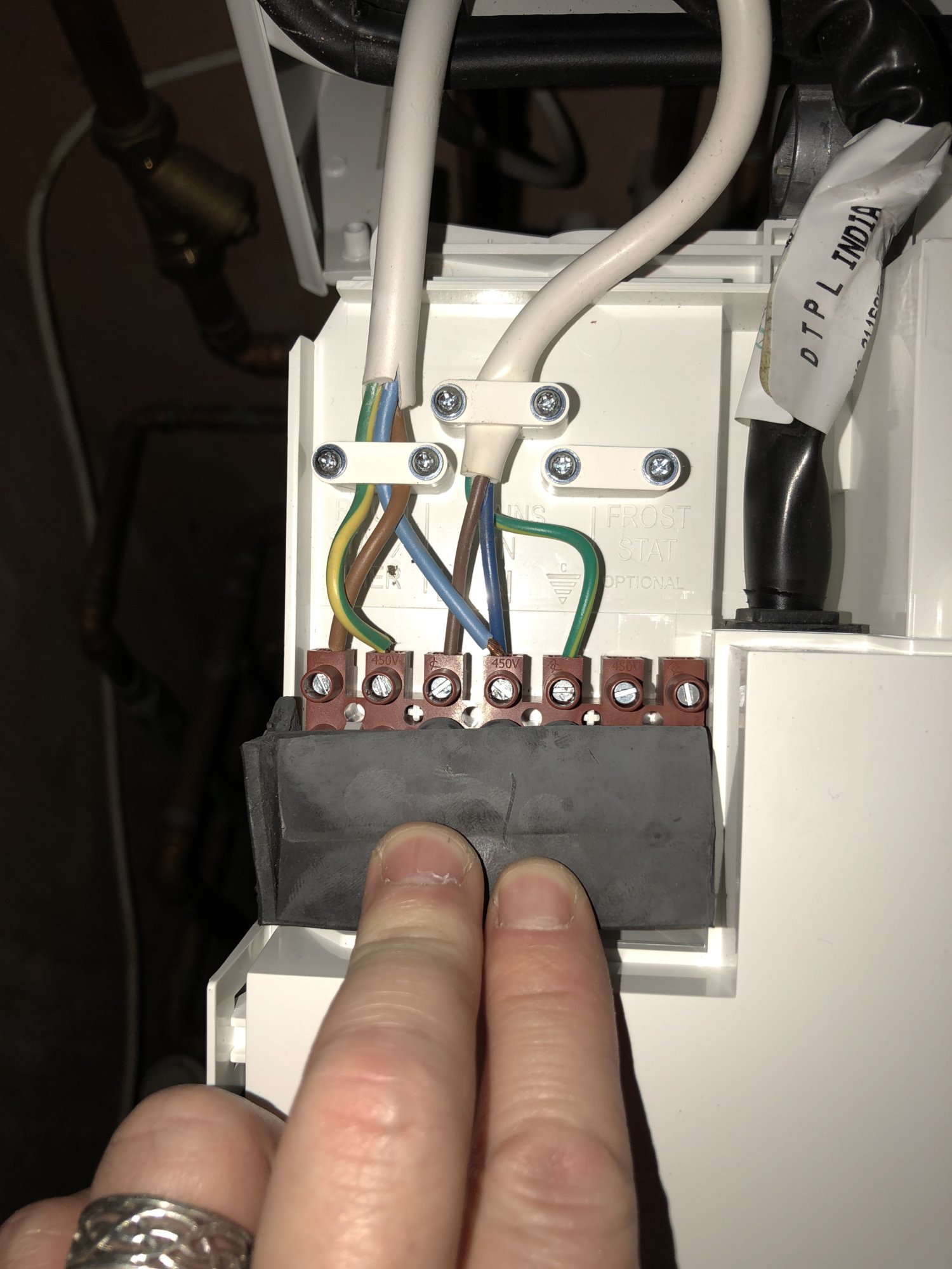
Help with logic 30 Combi and hive wiring please DIYnot Forums

ICM455 ICM Controls Manualzz
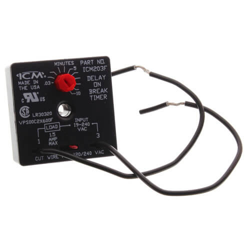
Ignition Control Module (ICM) Teardown FYI TeamTalk
Weil McLain CGa gas fired boiler wont fire Community Forums

2000 e450 super duty speedometer..odometer..a wiring diagram..meter
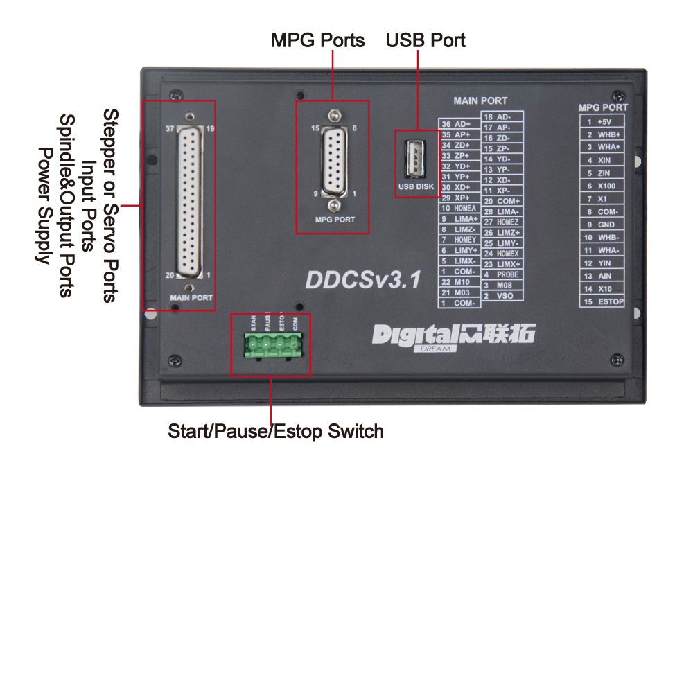
CNC Motion Controller DDCS V3.1_DDCNC
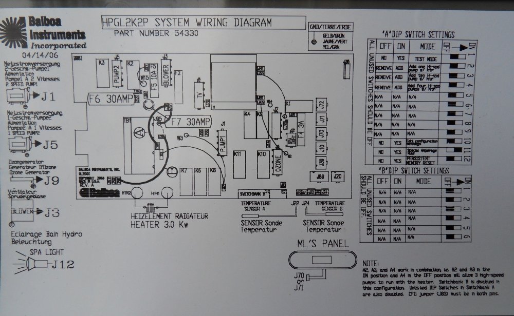
ERROR CODE cfe j82 hydropool balboa M7 GL2000 Portable Hot Tubs & Spas Pool and Spa Forum

Schéma electrique fiat ulysse 2 boisecoconcept.fr
ICM450 and ICM450S ICM Controls
Icm Controls Icm450 Wiring Diagram
Autórádió bekötés Elektrotanya
Icm Controls Icm450 Wiring Diagram
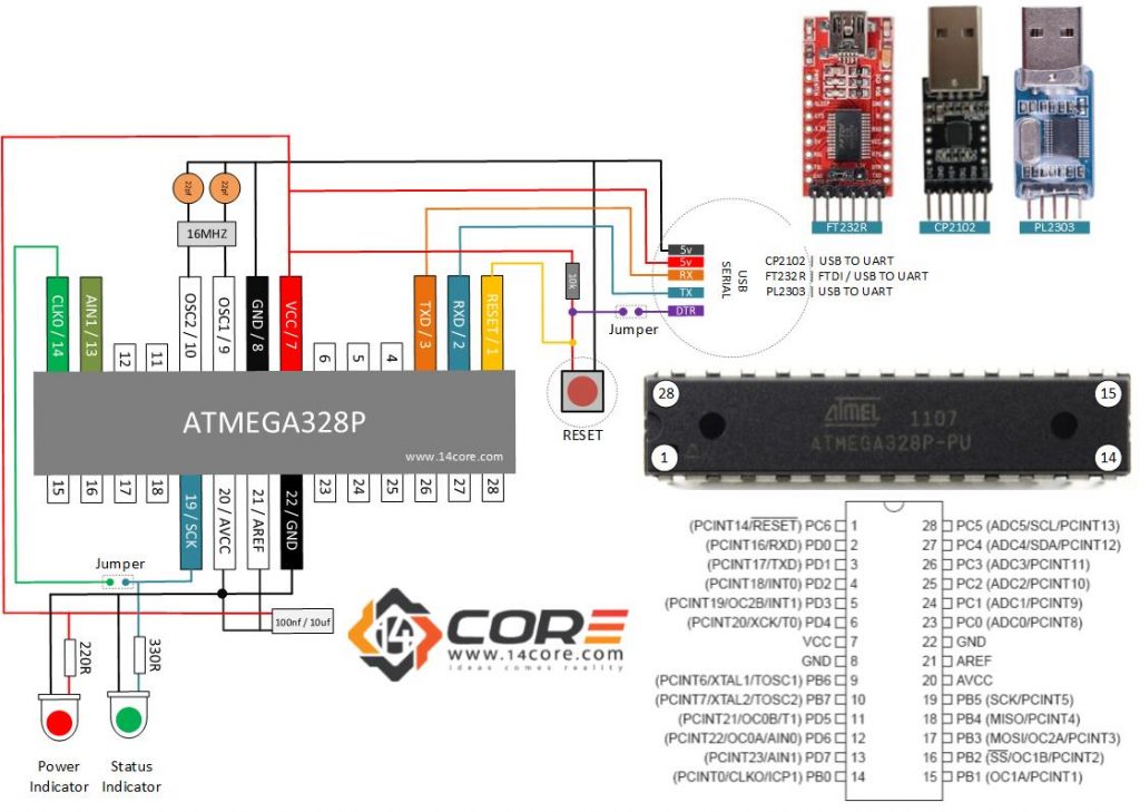
Wiring a Stand Alone ATMEGA328P CMOS 8Bit Microcontroller

2000 e450 super duty speedometer..odometer..a wiring diagram..meter
Icm Controls Icm450 Wiring Diagram
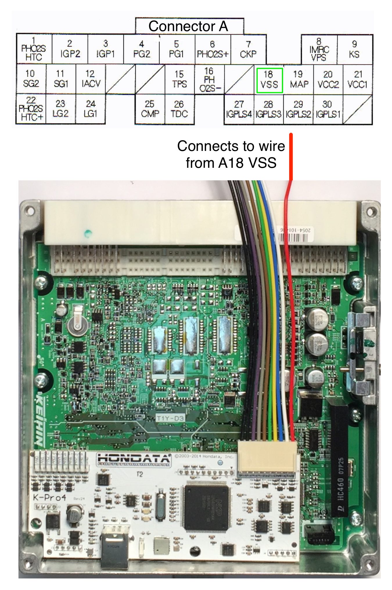
Technical Information KPro Alternative ECU for Engine Swaps
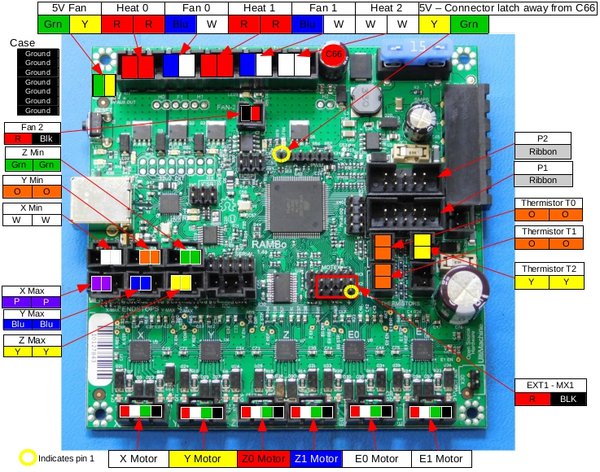
OctoPrint Micro Panel
ICM 450 Wiring Diagram

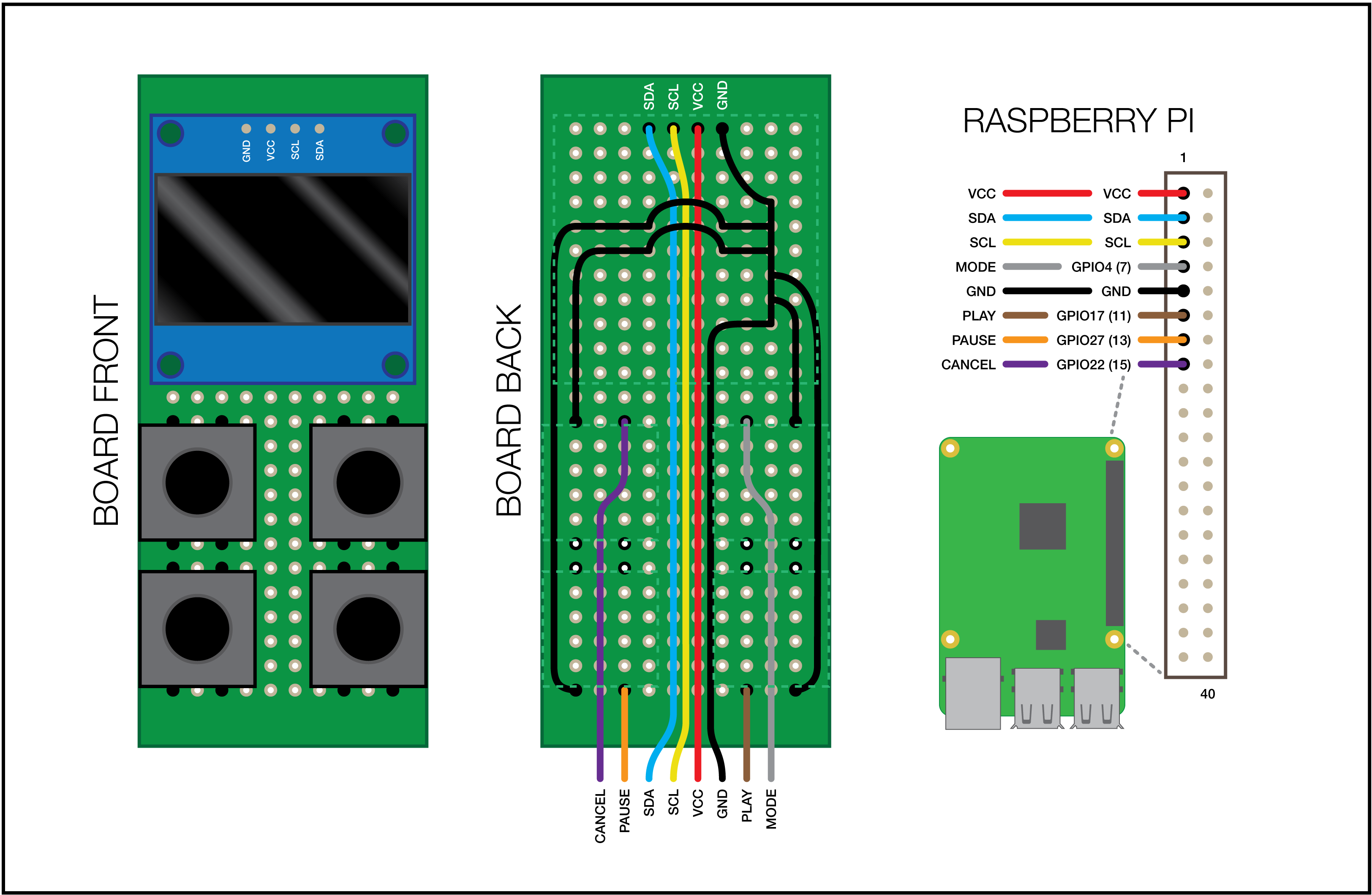
OHAI Open Hardware Assembly Instructions


